Dental implant stability refers to a measure of the immobility of an implant, indicating healthy integration of the implant with its surrounding bone. Placing or receiving dental implants is a grueling and stressful process with a lot of risks and uncertainties. Dentists must evaluate implant stability regularly to make critical decisions, such as crown placement to receive bite load, additional time for the bone to heal, or removal of a failing implant. Throughout the lifetime of an implant, dentists monitor its stability to evaluate implant health.
There are several ways to measure dental implant stability. One way is to use X-ray or CAT scan. This method is expensive and only gives partial information. It may also pose health concerns due to excessive exposure of radiation. The other way is to use resonance frequency analysis (RFA). The basic idea is to measure resonance frequency of an implant in bone. Since the resonance frequency depends on the stiffness of the bone-implant system, stability of the implant can then be inferred from the resonance frequency measurements. The RFA, however, has produced mixed results from clinical practices, as revealed in dentistry literature. There are strong needs for a more credible and reliable solution to determine dental implant stability.
My research goals for this project are (a) to demonstrate the inability of using RFA to identify dental implant stability, and (b) to develop a new method that quantifies dental implant stability by measuring angular stiffness of the implant-bone system.
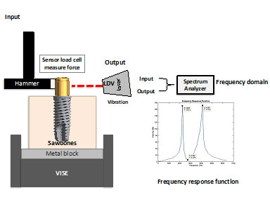
Figure 1. Specimen, experimental setup, and sample test results in the form of frequency response function.
To realize these research goals, we conduct experimental measurements and finite element analyses on the following setups. The model consists of a synthetic bone block, an implant, and an abutment; see Fig. 1. The synthetic bone is from Sawbones® with three different densities (15-PCF, 40-PCF, and laminated 40/20-PCF) to simulate various types of bone. Two types of implants are investigated: (a) regular platform (RP), 4 mm in diameter and in lengths of 8.5, 10, 11.5, 13, 15 and 18 mm, and (b) wide platform (WP), 5 mm in diameter and in lengths of 8.5, 11.5, 15 and 18 mm. The abutment can be a locator abutment (LA) or an impression coping (IMP).
Figure 1 also illustrates the experimental setup to measure resonance frequencies. An impact hammer excites the implant into vibration and a load cell at the tip of the hammer measures the excitation force. A laser Doppler vibrometer (LDV) measures the velocity of the vibrating implant. At the same time, a spectrum analyzer processes the measured force and velocity to obtain a frequency response function (FRF) of the implant-Sawbones® test model (Fig. 1). Each frequency at which an FRF peaks is a resonance frequency of the implant-Sawbones® test model and the lowest resonance frequency is recorded. At the same time, a finite element model is created to model the test specimen; see Fig. 2.
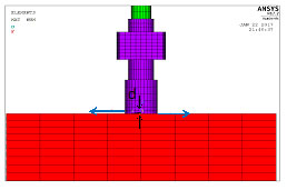
Figure 2. Finite element model of the experimental setup
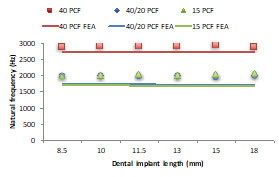
Figure 3. Comparison of measured and predicted resonance frequencies
Figure 3 shows a comparison of the measured and predicted resonance frequencies for implant of 6 different lengths. It is expected that implants with longer length have higher stability. Nevertheless, both the experimental measurements and the finite element predictions indicate that the resonance frequencies are independent of the implant length. This conclusion, of course, proves the inability of using resonance frequencies to identify implant stability.
Angular stiffness at the shoulder of the implant serves as a much better indicator of implant stability. As shown in Figure 3, the finite element predictions agree very well with the measured resonance frequencies. Therefore, the finite element model in Figure 2 can be used to estimate the angular stiffness. By applying a pair of equal and opposite forces, we calculate the rotation of the abutment center line. The moment produce by the forces divided by the rotation gives the angular stiffness of the implant.
Figure 4 shows the angular stiffness of implants of 6 different lengths (i.e., 8.5, 10, 11.5, 13, 15 and 18 mm), three different types of synthetic bones (i.e., 15-PCF, 40-PCF, and 40/20-PCF), and two types of abutments (i.e., locator abutment and impression coping). The results in Figure 4 show that implants with longer lengths have higher angular stiffness. Implants in synthetic bone with higher density has higher angular stiffness. These results indicate that angular stiffness is a much better indicator of implant stability. Moreover, when different abutments are used, the angular stiffness remains the same. This implies that angular stiffness is robust and is independent of the abutment used.
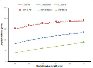
Figure 4. Angular stiffness for implants of 6 different lengths, two different types of abutments, and three types of bone
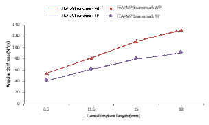
Figure 5. Angular stiffness for implants of 4 different lengths, two different types of abutments, and two different implant diameters
Figure 5 shows the angular stiffness for implants of 4-mm and 5-mm diameters. The implant with the larger diameter has higher angular stiffness. This implies that angular stiffness is a universal measurement of implant stiffness, that is, angular stiffness can be used to assess stability of different implants that are not necessarily in the same family.
Representative publications
- N. Khouja, W. C. Tai, I. Y. Shen, J. A. Sorensen, 2019: “A critique of resonance frequency analysis and a novel method for quantifying dental implant stability in vitro,” International Journal of Oral & Maxillofacial Implants, Vol. 34(3), pp. 595-603.