
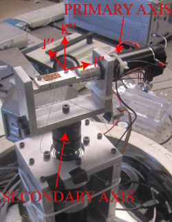
To experimentally validate the forewing model, a two-axis rotation stage was constructed (Fig. 1). The model is validated two rotation configurations at a time (pitch/roll, roll/yaw, pitch/yaw). Precision PID controlled servomotors are utilized to generate sinusoidal motion profiles along the two axes. Structural components are made of rigid aluminum to minimize vibrations of the stage itself. Experiments occur in both air and in vacuum to show a clear deconvolution of aerodynamic and inertial-elastic forces. The nominal pressure of the vacuum chamber is approximately 200 milliTorr.
A thin aluminum triangular wing is constructed, and a strain gage is mounted near the wing root in the spanwise direction. The quarter bridge strain gage circuit is completed with a bridge completion module, and the voltage signal is amplified using a strain gage amplifier. The temporal voltage signal is recorded at a rate of 1 kHz via a NI MyDAQ, which is controlled using Labview software. The resulting voltage is interpreted into strain in Matlab using a mathematical relationship.
The experiment has shown several important results. First, it has corroborated the notable effect of gyroscopic forces on dynamic bending. In the pitch-yaw configuration, gyroscopic forces were found to have as much as four times larger an effect on the strain than inertial forces. As shown theoretically, these gyroscopic forces tend to act at twice the driving frequency. Second, the experiment has shown that for this particular wing and rotation trajectories, aerodynamics constitutes maximally 15% to the strain. This indicates that the inertial-elastic assumption is appropriate in some contexts. Lastly, the experiment shows the inertial-elastic forewing model can predict physical quantities such as strain within reasonable accuracy. As a result, the model may be used to inform flapping wing MAV designers moving forth, particularly in the area of strain-based control mechanisms.
Download all experimental data and accompanying MATLAB scriptsAlso included is the CAE model of the experimental wing and the MATLAB script used for theoretical predictions of strain. Please refer to the included ‘read-me’ file for additional documentation.